DC Electronic Load V1.0
Overview
A DC electronic load is a tool that can be used to test power supplies and batteries. The basic operation of an electronic load is that it tries to maintain a set current through the load no matter what the supply voltage is set to. This is useful to find battery characteristics such as Amp Hour rating, or a power supply’s transient response, load regulation, etc...
This particular electronic load has wireless capabilities using Bluetooth® technology that enables it to be controlled remotely through a PC, as well as the ability to sample and log the data on the PC side, to generate characteristic charts and perform automated tests on the supply under test.
This section will discuss the main design aspects and the process of creating such tool. In particular: the circuit and enclosure design as well as the main responsibilities of the firmware. It will also explain how the computer software operates and how it tests a power supply automatically. It will also highlight the main problems faced while developing the system and their solutions.Type your paragraph here.
General Overview and Design Approach
This tool is created to help technicians to test power supplies efficiently without any frustration. One assumption made when designing this tool is that the user is informed and knows basic electronics concepts such as ohm’s law, power dissipation, load regulation, internal resistance, etc...
The following specification list highlights the main requirement of the unit:
- Operate between 1.0mA – 2.000A
- Safe to use by limiting:
- The input voltage to 25V maximum.
- The power dissipated to 30Watts maximum.
- The heatsink’s temperature to 95°C.
- Wirelessly send data to a PC (via a Bluetooth® link) to be logged to generate charts accordingly.
- Wirelessly receive commands from a PC (via a Bluetooth® link) to perform different actions.
Block Diagram
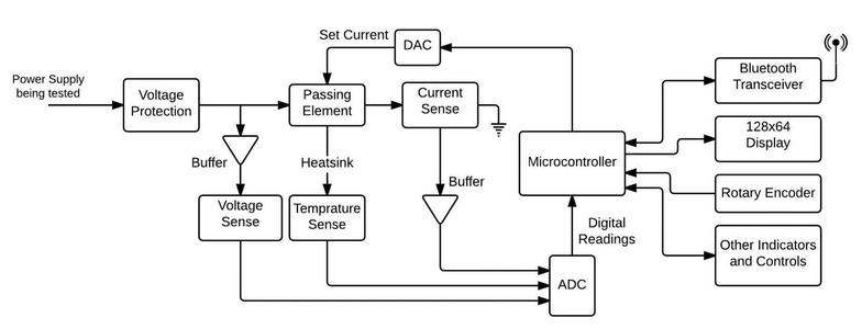
The block diagram shown below demonstrates the basic operation of the entire system, followed by a detailed description of each block
 Figure 1
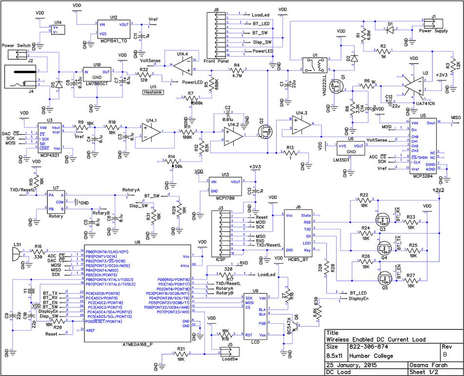
 Figure 2