Autopilot 500-TS
Overview
If you have spent time on Microsoft® Flight Simulator X, then you know you always wished you had some actual control panels in front of you instead of clicking on a computer screen. Even though there are many professional products out there that do the same job, I decided to design my own. I thought I would start with an Autopilot panel, because it's the most I use -- since I am a newbie non-pilot --. If this works out nicely, I might consider designing more panels for the simulator.
Layout
I wanted something that looks nice, and easy to use, but also small enough to fit on a desktop. The layout is not similar to the ones you see in a Boeing 737, or an Airbus A321, but yet modular and self explanatory. This layout is also easier to use by left handed people, such as myself.
The Front Panel
Figure 1 below shows a diagram of the interface design of the unit. I went with the horizontal design because I believe that it will make things easier to assemble, and fit better on my desktop.
 Figure 1
The layout is divided into multiple section. Each section is responsible for a certain aspect of the autopilot operation. The following explains all the operations supported by this unit:
- AP Master - To engage and disengage the Autopilot master switch.
- GPS/NAV - These two buttons toggle between the two modes, pressing any of them has the same affect.
- FD - Toggles the Flight Director instrument.
- ATHR - Toggles the Autothrottle mode, allowing the autopilot to control the power settings of the engines.
- SPD - Toggles airspeed hold to maintain the speed set using the Speed Dial on the right side of it.
- TO/GA - Toggles Takeoff/Go-around mode.
- ALT - Toggles the altitude hold to maintain the altitude set using the Altitude Dial on the far right side of it.
- LVL - When the ALT hold is enabled, pressing this button will set the autopilot maintain the current altitude of the airplane. Pressing and holding this button while the unit is booting up will enter Test Mode. In this mode the user can test all the switches, dials, LEDs and displays.
- APR - Toggles APR Mode used for ILS, VOR and GPS approaches.
- HDG - Holds the heading angle set by the heading dial on the right side.
- B/C - Enables Backcourse Approach, used for airports that don't have dedicated ILS transmitters for the flip-side of a runway. Holding this button for more than 500 milliseconds will enable Live Mode. While this mode is enabled, the displays show the actual live readings of the instruments rather than the autopilot settings.
- LOC - Enables GPS navigation, allowing the autopilot to cruise according to the GPS paths.
Design Approach
The unit is divided into two boards; a Controller Board and a Display Board. The controller board has all the main circuitry, including the Micro-controller. it also contains all the button and switches as well as the LEDs. while the Display Board contains all the 7-segment displays. However, both boards contain rotary encoders. The reason it is divided into two board is because the height of the components does not line up nicely to show on the other side of the front panel.
 Figure 2
Schematic Design
Controller Board
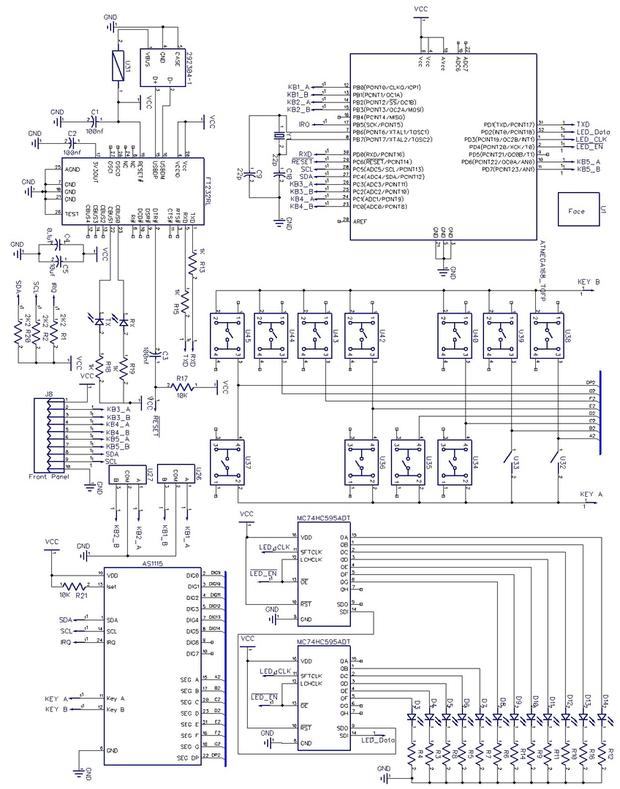
The biggest challenge I faced is controlling all these inputs and outputs with using a small Microcontroller (ATMega 328). This controller has a limited number of I/O pin, therefore I had to use three AS1115 and shift-registers to control everything serially.
 Figure 3
Controller Board
The panel has 13 switches to toggle the different modes on and off. they are scanned using AS1115 which in turns, interrupts the µC every time a switch is pressed. The µC reads the value of the switch from the AS1115 and acts accordingly. I did not include the diods to let the chip differentiate the values when multiple switches are pressed simultaneously, thinking that in this application it is not needed. I came to regret that decision when I realized (too late) that if one of the 2 toggle switches is toggled on, it will prevent all the other buttons from working. A work-around for that (for this version of the panel) is toggling those switches on then directly off, which makes them act like momentary switches instead of toggle switches. If I create a V2.0 of this panel, this problem will be properly addressed.
LED Indicators
The panel has 12 LED indicators that display the state of the autopilot (in terms of what's toggled on or off).
They are controlled using 2 shift registers M74HC595, the µC sends serial data, and the shift registers output parallel data, simple and straight forward. I could have used the key-scanning chip to handle the LEDs along with the switches. but I have decided to take the shift register path to ensure that the keys-canning chip has only one job without any distractions.
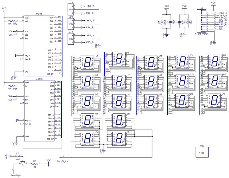
Display Board
This board contains all the 7-segment displays and 3 of the rotary encoders. It connects with the main board using a 10-pin connector. This connector transfers the power line (Vcc, GND), I²C bus (SDA, SCL) , and 6 lines for the 3 rotary encoders.
 Figure 4
7-Segment Displays
The panel has 19 digits that display values such as set altitude, vertical speed, course, etc...
From these 19 digits, 4 of them are always displaying 0 (as far as the simulator goes when it's set to imperial system), therefore they are there just for completion but require no processing whatsoever except turning them on and off. This gives me 15 digits to handle, the way I'm doing that is by using 2x AS1115 chips. Each one can handle up to 8 digits, which gives me a total of 16 digits to be controlled, I only need 15. The controller uses I²C bus to communicate with the µC. It also has self addressing mode where it allows up to 4 devices on the same bus.
PCB Design
After deciding on the box enclosure (Hammond - 1595EBK) I had the exact dimensions to able to design the layout of the front panel. Since the boards are mounted directly on the front panel, placing the component where they match with the openings on the panel was the first step of the PCB design. The two boards sit next to each other, but at different heights from the front panel. The following figures show the PCB layout and the 3D model of the boards and how they are mounted on the front panel.
 Figure 5
 Figure 6
 Figure 7
Firmware
Making the panel talk to the simulator was supposed to be a challenge, even though simulator comes with an SDK to handle this type of communication. However there is a brilliant tool out there called Link2fs Multi FSX made by a man named Jim and it does a beautiful job. I am using Link2fs Multi FSX tool for the time being until I develop my own software to talk to the simulator.
The µC is loaded with an Arduino - Uno bootloader, it uses the following libraries:
- AS1115.h - by Sarahemm, to communicate with the 7-Segment and keyscanning chips. I had to modify the library to support key-scanning, and fix a few issues with the font initializing and intensity change.
- WSWire.h - by Nicholas Zambetti, to replace the default arduino Wire.h. It provides timeout error returns that helped me solve an I²C bus causing the whole program to freeze.
- Quadrature.h - by Keith Neufeld, to handle the rotary encoders input. I modified the libarry slightly to make it work with analog pins as well as digital pins.
The rest of the firmware is written by myself to handle reading and writing from/to Link2fs Multi FSX which in turn talks to the Flight Simulator. Click here to view the complete source code.
Gallery
Some photos I took while assembling/building the autopilot.